Networking Fundamentals – Part 2

Repeater: A repeater’s job is to repeat an electrical signal. The form that our data has taken to be sent across a cable is one’s and zeros. The repeater takes an incoming signal and then generates a new clean copy of that exact signal. This prevents maximum cable lengths from stopping transmissions and helps ward off attenuation; the gradual weakening of a signal.

Hubs – only one PC at a time can send data; if multiple PC’s are connected to a single hub, it’s One Big Collision Domain. To prevent collisions, a host will use CSMA/CD (Carrier sense multiple access with collision detection).

CSMA/CD:

  • carrier sensing scheme is used.
  • a transmitting data station that detects another signal while transmitting a frame, stops transmitting that frame, transmits a jam signal, and then waits for a random time interval before trying to send that frame again.

Bridge – used to create smaller collision domains. Place a bridge between multiple hubs. More collision domains is more beneficial. Segmenting the collision domains does not reduce the amount of broadcasts (for example, multiple hubs separated by multiple bridges is still one big broadcast domain). Every single host will receive a broadcast.

Broadcasts are not a bad thing, broadcasts can be beneficial by providing routing updates. But we do want to lower the number of broadcasts.

Switches: each host is in it’s own collision domain. Collisions cannot occur. Each host has more bandwidth available; not sharing bandwidth. Theoretically each host can run at 200mb (100mb sending, 100mb receiving with full duplex). Switches by default do not break up broadcast domains. Microsegmentation is a term sometimes used with Cisco documentation to describe the one host/one collision effect.

A switch will do one of three things with an incoming frame:

  • Forward it
  • Flood it
  • Filter it

The switch looks at it’s Mac address table to check if there is an entry for the destination MAC address, but first the switch will look to see if there’s an entry for the source MAC address in the frame. The switch uses the source MAC address to build the table. You can statically configure MAC address tables but not recommended.

#show mac-address-table    —   The command we use to look at the mac address table on a switch.

An unknown UNICAST frame is always flooded. – If an unknown unicast frame has to hit 79 other ports in an 80 port switch, it can cause a bit of overhead on the switch/cpu.

#show mac-address-table dynamic

If the switch does not have an entry for the destination mac address, and a host replies to the flood with the correct response, the switch will create an entry for the new host.

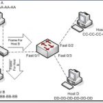
Take into consideration the following diagram:
SwitchFilterExample
click image to enlarge

In this instance, hosts A and B are in the same collision domain, separated by a hub. When Host A sends out a frame destined for Host B, and the frame arrives at the switch, the switch looks at it’s dynamic MAC address table and sees that the frame is destined for the same port as it’s origin. In this case the switch will FILTER the frame (drop the frame):
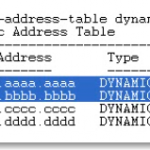
MacTableFilterExample
Click to enlarge image

Switches never send a frame back out the same port from which the frame arrived.

Flooding: When the switch has no entry for the frame’s destination MAC address. The frame is sent out every single port on the switch except the one it came in on. Unknown unicast frames  are always flooded.

Forwarding: when the switch does have an entry for the frame’s destination MAC address. Forwarding a frame means the frame is being sent out only one port on the switch.

Filtering: when the switch has an entry for both the source and the destination MAC address; the MAC table indicates that both addresses are found on the same port. (See image above)

Broadcast frames: a frame that is sent out every port on the switch except the one that received it. Broadcast frames are intended for all hosts, and the MAC broadcast address is ff-ff-ff-ff-ff-ff.

We can statically configure a port with a MAC address but not best practice. Dynamically learned MAC addresses will age out with a default of 300 seconds (5 minutes).

Command to see help for the tables is

#mac-address-table ?

then

#mac-address-table aging-time ?

0-0 Enter 0 to disable aging (not a good thing to do)

10-1000000 Aging time in seconds

The benefit of Dynamically configured MAC addresses is that if the host is not seen in 5 minutes or the interface goes down; physical damage to the port, when the host is connected to a different port, the switch will dynamically update the table with the source. The current entry will be aged out. Let the switch do it’s work, and use dynamically assigned addresses.

When the switch forwards, floods, or filters the frame, there is another decision to be made – how will the forwarding be processed?

Three different processing options:

  • Store-And-Forward
  • Cut-Through
  • Fragment-Free

Store and Forward is the default method on newer switches. The entire frame is stored and then forwarded.

Store and Forward – uses FCS – allows the recipient of the frame to determine if the data was corrupted during transmission (error detection). In the incoming frame the switch will read the destination MAC address before it looks at the FCS. The switch can check the FCS before forwarding the incoming frame. Gives us more error detection than the other two methods above.

Cut-Through – switch reads the MAC addresses on the incoming frame, and immediately begins forwarding the frame before rest of the frame is even read. Cut through is a lot faster. Cannot check for damaged frames.

Fragment-Free (middle ground for speed vs. error detection) works on the presumption that the corruption will be found in the first 64 bytes of the frame for damage. If no damage, then the forwarding process will begin.

Use virtual LANs to segment a network into smaller broadcast domains. In a production network, you can have a lot of hosts and each host can send out broadcasts with a cumulative effects. Hosts tend to respond to Broadcasts with a Broadcast of their own.

Broadcast Storm: can max out a switch’s resources (memory and cpu) making the switch useless. But before this, broadcasts may take up most of the bandwidth.

Create multiple broadcast domains to limit the scope of a broadcasts.

Basic command to view vlans is

#show vlan

but for practical use, the command below is better:

#show vlan brief

By default, you will have a single vlan on modern cisco switches.

To put for example two hosts in a separate single vlan (broadcast domain),

#conf t

#interface fast 0/2

#description Connected to Host 2

#switchport access vlan 24

#switchport mode access    — to makes access to only one vlan – no trunking

then

#int fast 0/4

#description Connected to Host 4

#switchport mode access

#switchport access vlan 24

#^Z

#copy run start

#show vlan brief

Once host2 and host4 are on the same vlan they won’t be able to ping other hosts on other vlans.

No traffic – pings or data packets can be sent from one VLAN to another without intervention of a Layer 3 device; most likely a router.

 

Networking Fundamentals – Part 1

In these posts, we will document the fundamentals of networking. We will begin with the basics, including the OSI model, and work our way up from Layer 1 to layer 7, but mostly concentrating on Layers 1-3.

As many have learned, the path to success in troubleshooting networks is knowing and understanding the fundamentals.

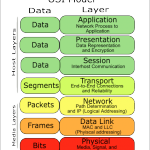
OSI (Open Systems Interconnection) model:

osi model
click to enlarge

Layer 7: Application Layer:

End users are interacting with the layer itself. When a user is being authenticated, that user is interacting with layer 7. If encryption is taking place, that is layer 6. The application layer determines if a remote communication partner is ready. For example if a modem is in use, the application layer asks if the modem is ready. Agrees on procedures for communication; data integrity, privacy and error recovery. Protocols running at layer 7: SMTP, POP3, Telnet, HTTP, FTP, SNMP.

Layer 6: Presentation Layer:

Formatting of data. For example if Word opens a file in gobbly gook, that is a presentation layer issue. No agreement has been made for formating. Compatability with the OS, ASCII, Binary, compression. JPG, MIDI, TIFF. Any file type is how data is being presented.

Layer 5: Session Layer:

Handles creation, maintenace and tear down of communication between hosts. The communication itself between two hosts is called a session. Sessions can be short. The session layer manages communication. Provides Full Duplex, Half Duplex, or Simplex. The Session Layer is commonly implemented explicitly in application environments that use remote procedure calls.

Layer 4: Transport Layer:

Establishes end-to-end connection between two systems. Session data is received from the upper layers and the transport layer makes sure the data gets to the destination in the correct sequence, and without errors. TCP (Connection-oriented) and UDP (Connectionless) are two methods of transporting data at the Transport Layer.

Layer 3: Network Layer:

IP runs at this layer, routers at this layer (routing layer), IP addresses, layer addresses, etc. Routing is a two question process: Is it a Valid path? And what is the Best Path to get there?

Layer 2: Data Link Layer:

This is where our switches and bridges run. WAPS also operate at this layer. Cable modems/DSL modems. Ethernet, HDLC, PPP, Frame Relay. There is a big difference between error detection and error recovery. Layer 2, we have error detection with FDS Frame Detect Sequence. MAC addresses/Hardware addresses/Physical Addresses/Burned In Address (BIA) are at Layer 2. There is such a thing as a layer 3 switch; a single device that can do the routing and the switching.

Layer 1:  Physical Layer:

1’s and 0’s. The Physical Layer handles the actual data being transmitted. Cables, pins, voltage running at physical layer.

TCP:

  • Guaranteed Deliver
  • Error detection via sequence and ACK numbers
  • Windowing
  • Connection Oriented

TCP Three-way handshake: SYN, SYN-ACK, ACK.

Error detection is finding an error.

Error recovery is doing something about the error.

For example some layers have error detection – layer 1, but not error recovery.

In transmitting several segments, when the recipient sends the ACK number, it sends the next number in the sequence that the recipient expects to receive. An acknowledgement timer will re-send: Positive Acknowledgement with Retransmission (PAR).

Windowing is the amount of data that the sender is allowed to transmit without waiting for an ACK. The recipient decides the size of the window. This gives the recipient the ability to decide the amount of data flow. (Flow Control) Sliding Windows refers to dynamic adjustment of the size of the window itself.


UDP:

  • Best effort delivery but no guarantee of delivery
  • No error detection
  • No windowing
  • “Connectionless”

Cables:

Crosstalk – EM interference; a signal crosses over from one cable to another. Can be described as Near End Cross Talk (NEXT) or Far End Cross Talk (FEXT) depending on which end of the cable is being tested. PSNEXT is Power Sum Near End Cross Talk which is the calculation made when a NEXT test is run. When the NEXT result for each pair of wires is added, the result is the PSNEXT. (Not to be confused with the management software titled PSNEXT).

Straightthrough cable – used to connect a PC to a switch or a hub. The wire connected to Pin 1 on one side is connected to Pin 1 on the other, the wire connected to Pin 2 on one side is connected to Pin 2 and so forth.

CrossOver Cable – typically used between two switches, and when two switches are transmitting data over the same pair of wires, a crossover cable is used. A switch to switch connection with a CrossOver Cable is also called a TRUNK.

Rollover Cable – All eight wires in the cable will “roll over” to another pin at the remote end. eg. Pin 1 at one end rolling over to pin 8 at the other end. Pin 2 rolling over to pin 7 etc. Typically Blue Cisco cables that come with each Cisco router with a DB9 connector are Rollover cables. (Get a USB adapter so that you can use it with your laptop). These cables typically connect to the console port on the switch/router.

MAC address – Media Access Control Address (Also known as Ethernet/NIC/LAN/Physical/BIA address): used by switches to send frames to the proper destination. 48bit address.

The MAC address has two parts, the first being the Organizationally Unique Identifer (OUI). The OUI is assigned to hardware vendors by the IEEE. A given OUI is assigned to one and only one vendor. The second half of the MAC address is a value not yet used by that particular vendor.

The Broadcast MAC address: 77-77-77-77-77-77

The Multicast MAC address always starts with 01-00-5E, then 00-00-00 thru 7F-FF-FF


Outlook 2010 – Cannot create new profile; An unknown error occurred, error code: 0x80070057 – Solved!

One of our Windows 7 Pro, 32 bit users (not SP1), experienced Outlook 2010 failing on a regular basis. The client was setup with Auto-discover and the application would crash / freeze/ hang randomly as well as could be made to crash by going into the Calendar, create a New Meeting->Scheduling Assistant -> and enter another user’s name.

Additionally, we tried closing Outlook, going to the Control Panel and chosing the Mail applet. Click on Profiles -> Profiles -> Show Profiles… -> Add…

The Outlook wizard would start, but then fail with the error message:

“An unknown error occurred, error code: 0x80070057”.

The Event Viewer (Local) -> (Windows Logs: Application) would have a cryptic message with the following information:

Event 1000, Application Error

Faulting application name: OUTLOOK.EXE, version: 14.0.4760.1000, time stamp: 0x4ba8fefdFaulting module name: OUTLOOK.EXE, version: 14.0.4760.1000, time stamp: 0x4ba8fefdException code: 0xc0000005Fault offset: 0x0054ac63Faulting process id: 0x1174Faulting application start time: 0x01cc0e56a826f1c7Faulting application path: C:Program FilesMicrosoft OfficeOffice14OUTLOOK.EXEFaulting module path: C:Program FilesMicrosoft OfficeOffice14OUTLOOK.EXEReport Id: 375d88cc-7a62-11e0-a74c-b8ac6fc5d92c

Running a search on these errors produced a lot of options for repairing the problem including checking OWA IIS certificates, installing .NET on the exchange server, Exchange SP2/SP3,  editing your hosts file, Exchange PowerShell setting virtual directory, and the list goes on.

The solution that resolved this issue finally for us was to install on the Outlook client, the hotfix created by Microsoft here: http://support.microsoft.com/default.aspx?scid=kb;en-US;2281463

The download is not easily accessible on this page, so don’t be discouraged and go ahead and “View and request hotfix downloads” from the link at the top of the page.

This link will send you to a Hotfix Request page where you place a checkmark on the update you wish to download. Be careful because if you visit the page with a x64 machine, you will most likely be prompted to download the x64 client. It’s best to visit the hotfix page on the client that has the problem. Enter your email address and then confirm. Type in the captcha and then hit “Request hotfix.” You will be quickly emailed the link to the hotfix download as well as a password.

*Note: Prior to installing a hotfix of this nature, it is always recommended you backup your system (Windows 7 backup is a pretty good free image-based backup, my next best recommendation is something like Acronis 10.) Also, it is a good idea to take a manual System Restore point: Start -> Right-click on Computer, choose Properties, System Protection, Create.

Once the hotfix has been downloaded, when you try to run the .exe you will be prompted for the password for the file to run. Enter the password that was emailed to you and complete the setup. After the hotfix completes, for good measure, go ahead and reboot. After the restart, keep Outlook closed and go back to the Mail control panel applet. Go to Profiles ->Show Profiles… -> Add… and create a new Outlook Profile. Under “When starting Microsoft Outlook, use the profile: -> Always use this profile -> Hit the dropdown for the newly created profile.

Start Outlook. This will create a new Outlook profile for the user. Also, a new .ost file will be created which if the mailbox size is large, it may take a considerable amount of time to rebuilt the new profile. You may need to visit the old profile in the Control Panel Mail Applet to see if any data files were attached or settings/signatures were modified or need to be created or copied to the new profile.

You can test to see if the application crashes by visiting the Calendar Scheduling Assistant.

SBS Server 2003 network connection NIC unresponsive. Solved!

After several restarts/reboots, a Small Business Server 2003 would not respond to pings, and was holding a network hostage by not servicing DNS requests. When trying to repair the Local Area Connection, the following error occurred: “Windows could not finish repairing the problem because the following  action cannot be completed:
Clearing the ARP cache”

After starting/stopping the Routing and Remote services service, and disabling/enabling the NIC in the Device Manager with no luck, we tried manually clearing the arp cache with the following actions:

Check the ARP table from the command line with the command:

arp -g

See if there are entries, and if so, delete them with the command:

arp -d *

This did not help and what did resolve/solve the issue was the following actions:

  1. Shut down the server (Start -> Shutdown)
  2. Once the server has completely shut down, remove the CAT5 Ethernet cable(s) from the Network Interface Card in the back of the server. Make a note which NIC port(s) the cable(s) are plugged into if there is more than one.
  3. Remove the power cable(s) from the back of the server. With both the power and Ethernet cables unplugged, press the power button on server to flush all electricity from the motherboard and interface cards.
  4. Replace the power and Ethernet cables, and power up/start the server normally. In our case the server began responding to pings and started running normally.
  5. After logging in, check to see that all services have started that are set to Automatic. To do this, go to Start -> Administrative Tools -> Services. Sort services by Startup Type. All of the services with the Startup Type: Automatic should be in the “Started” status (except for some that normally stay stopped like Performance Logs and .NET services).

Hopefully this tip will save you some frustration from wrestling with a non-responsive NIC or hunting down Microsoft hotfix updates.

A final note that if the unresponsive server is your primary DNS/DHCP server, and while it’s down clients are unable to get out to the internet or contact other network resources, you may wish to modify your DHCP client lease settings to include some (external) DNS servers other than your primary DNS/DHCP server.