Windows 7 networking basics – How to map a drive between two computers in a WORKGROUP – not joined to a domain

This how-to procedure for mapping network drives pertains to Windows 7 PC’s that are not joined to a domain, but are members of the same network Workgroup. This how-to map network drives is not the same as using the Windows “HomeGroup” feature – this tutorial is a little more advanced – but the method works for me consistently.

  1. Make sure that both computers are on the same network and subnet. This should be already done in most cases as your computers should pick up IP addresses and network settings from a DHCP server/router/modem. Things might get weird if each PC trying to reach one-another are on different connections, i.e. one is on WiFi and one is on an Ethernet cable. Essentially both machines should have IP addresses that look similar, something like 192.168.0.5 and 192.168.0.6. You can find your IP address by right-clicking on the Network icon in the taskbar, down by the clock, or go into the Control Panel > Network and Internet > and choose: Network and Sharing Center > Change Adapter Settings > Right-click on Local Area Connection (the adapter which is connected to the network and internet) > Status > Details… button > IPv4 Address.
  2. Each computer should be able to ping one another by IP address and by hostname. In a command prompt (Start button > All Programs > Accessories > Command Prompt) you can test this with the following command to ping by IP address:
    ping 192.168.0.5

    You should receive “Reply from 192.168.0.5…” and not “Request timed out.” Again, this should be done from each computer to the other.

  3. Next determine what the computer name is for each computer. Do this by Right-clicking on the Computer icon in Windows File Explorer and choose Properties.
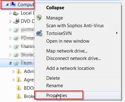
    Windows 7 Computer Properties

    Look for “Computer name:” – use this computer name to do another ping test. From a command prompt, type in:

    ping computername

    where you replace ‘computername’ with the name of the other computer you want to ‘talk to’. Again, you should get ‘reply from…’, not ‘error/no host/time-out’. If you get replies when you ping the IP address but not the computer name, then you can still map the drive/share from your computer, but it won’t look pretty.

  4. If you can ping by IP address but not computer name, for testing purposes, make sure the Windows Firewall is turned off (temporarily), and that both computers are members of the same Workgroup. In the same Computer Properties as above, where you found the Computer name: … you should see the “Change settings” link to the right of the Computer Name:. under the Computer Name tab, click on the “Change…” button > select Workgroup: and then enter the same workgroup name on both of the computers that will share files. Most people do Workgroup: WORKGROUP. Once you’re able to ping each computer from one another (at least by IP address), you should be ready to share out a folder and then map a drive letter to that share.
  5. Next, make sure that the folder you want to access on, for example, Computer Name: PC1 is actually shared out by the PC1 computer. In PC1 Windows file Explorer, Right-click on Computer and choose Manage.
Computer management

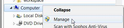
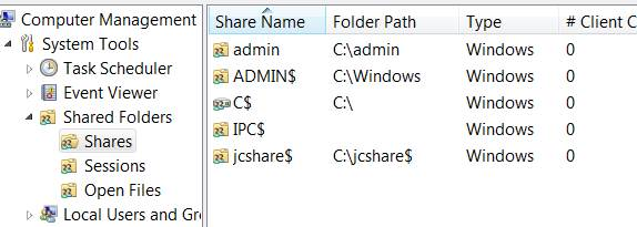
6. In the management tool, expand Shared Folders and then click on Shares:

Shared folders

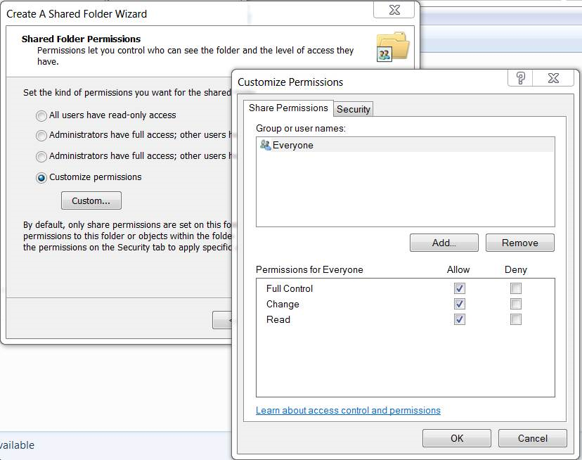
7. If you don’t see the folder you want to share listed, click on More Actions > New Share > follow the wizard (don’t worry about the offline settings.) Typically if you’re in an environment where you trust everyone, you can set the share to be accessible (read/write/execute) by Everyone (Everyone is the name of an actual user group that resides in all Windows computers). Do this by selecting “Customize Permissions” then place check-marks in Allow: Full Control, Change, Read > OK:

Windows 7 share permissions

If you’re wondering what the $ is for in the shares I have on my machine, the $ is used to hide a file share. If the folder name has a $ at the end, it’s hidden from people browsing the computer’s IP address or UNC name (explained later), but since you know it’s there you can still get to it. For example, in my shares screenshot above, I could browse to the share by typing in \\jasonPC\jcshare$ . But had I only typed in \\jasonPC\ then it would not be displayed.

8. Now that the share is available, from PC2 you can browse to the share by the UNC computer name (Universal Naming Convention used by all windows computers – in Apple/Mac’s it’s actually weird and to browse to a share on a Mac you would use smb://jasonPC/share.)

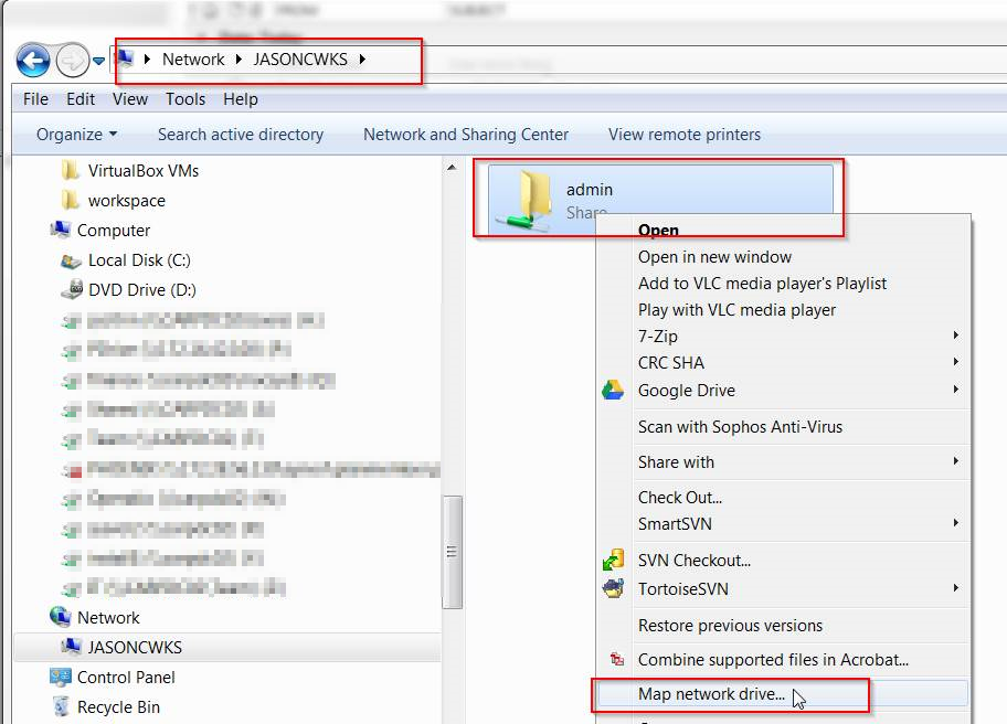
Open Windows File Explorer, in the address bar, type in the computer name that has the share you want to connect to preceded by two back-slashes (\\) and then followed by another backslash. So for example \\JASONCWKS\ and then hit the enter key. In the event if you could not ping the other computer by the UNC computer name, you can do the same action but replace the computer name with the IPv4 address, for example: \\192.168.05\ .

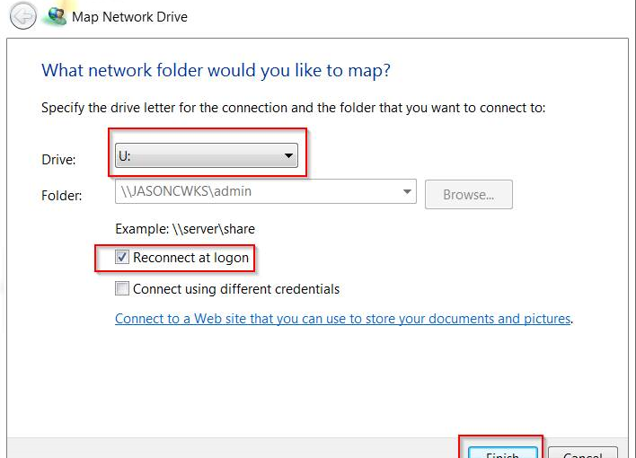
9. You will see a list of shares available on the computer. Next, right-click on the share and choose Map Network Drive.

Browse by UNC computer name

10. Now provide the drive letter you want, place a check-mark on Reconnect at Logon and then Finish

Map network drive

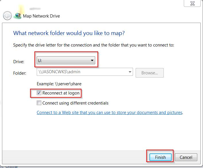
That’s about it! Your other computer should now have the drive mapped with full read/write permissions.

How to setup an Amazon AWS VPC, What is a VPC, and Subnets, Part 1 of 3

Amazon Web Services (AWS) provides the capacity to create a Virtual Private Cloud (VPC), which is a virtual network dedicated to your AWS account. In the first part of this three-part series, I will show you how to create a VPC with the corresponding subnets.

Read the rest of the articles Here

AWS VPC – Overview, setup, subnets

How to Install ISC DHCP Server on Ubuntu 16.04

The Internet Systems Consortium (ISC) Dynamic Host Configuration Protocol (DHCP) server is free, open-source, and easy to install. Both enterprises and small networks have used ISC DHCP in production for many years.

In this guide, I’ll demonstrate how to locate your current DHCP server and then install and set up an ISC DHCP server. We’ll then move on to gaining control of your new DHCP server, best practices, monitoring the logs, and setting up static address reservations.

Read the rest of the article here:

Install ISC DHCP Server on Ubuntu 16.04

OS X new domain migration – retaining user profile with terminal commands

If you’ve been tasked with the domain migration of a number of OS X El Capitan and Mavericks iMacs or MacBook Pro or Mac Air workstations, you may need to retain the user profiles. Normally, when unbinding, and then binding to a new domain, your user’s settings will be lost. You may be tempted to use Migration Assistant, but this usually requires copying the entire profile somewhere else which can take a long time and use a lot of disk space.

With this list of steps, you can use commands, scripting, and setting permissions and ownership of the user directories to perform the domain migration in-place.

Below is the sequence of commands and workflow step by step to migrate an OS X mac to a different domain. The key is to delete the sqlindex files, and prepare the user account for it’s new permissions. Please note the guide may not make sense at first while reading, but it will allow you to migrate your macs so that the users keep their same profile. Let me know if this guide helps you in your domain migration and if you find any better solutions.

Tasks Commands
1 Login as admin user and list users  Terminal -> ls -alh /Users/
2 move domain User folders to .old sudo mv /Users/johndoe /Users/johndoe.old
3 Unbind Machine  Preferences->Accounts->Login Options->Network account server -> Directory utility ->Active directory->Unbind
4 Delete sqlindex files found in ls /var/db/dslocal/nodes/Default/ sudo rm -f /var/db/dslocal/nodes/Default/sqlindex
sudo rm -f /var/db/dslocal/nodes/Default/sqlindex-shm
sudo rm -f /var/db/dslocal/nodes/Default/sqlindex-wal
5 reboot sudo reboot
6 Bind to new domain Preferences->Accounts->Login Options->Network account server -> Directory utility ->Active directory->Unbind
7 reboot
8 login as user
9 Logout and login as admin
10 move User folder .new After you have logged in as the user under the new domain you need to move the newly created User home folder to johndoe.new and move the .old User folder to /Users/johndoe with the command:
sudo mv /Users/johndoe /Users/johndoe.new
11 move .old to new username sudo mv /Users/johndoe.old /Users/johndoe
12 Change ownership of user home folder sudo chown -R johndoe:”Domain\Domain Users” /Users/johndoe
13 logout as admin
14 Reboot
15 login as that user (johndoe)
16 Click on “Create a new keychain” much easier in El Capitan and Yosemite If “Create new Keychain” fails then goto Keychain Access –> Preferences –> Reset Default Keychain

Configure Cisco 3750 Switch Port Team Channel and MacPro with Bonded Thunderbolt Ethernet LACP Link Aggregation

If you’ve got a new MacPro and want to utilize both of the two built-in Gigabit Ethernet ports (and possibly some Thunderbolt-to-ethernet adapters) in a bonded LACP Link Aggregation virtual adapter in conjunction with a Cisco 3750 switch, follow the instructions below.

The first part is configuring your switch to allow your Mac to create a bonded link. In my case, without first configuring the switch, I was able to create my Mac’s bonded ethernet adapters, but couldn’t pick up a DHCP address. I further went into the virtual adapter’s bond status and saw red dots and the messages “No Partner” and/or “Bad Link”. The problem was that I hadn’t setup my switch with the appropriate LACP protocol on it’s interfaces.

Here are the instructions for creating a bonded Ethernet LACP link aggregation from Apple: http://support.apple.com/kb/PH8356

Note that in the above article there are some requirements: you need at least one IEEE 802.3ad-compliant switch or another Mac OS X Server computer with the same number of ports.

So I configured a Cisco 3750 switch with a new channel group, and added 4 ports into the channel group so that we can bond 4 NICs for the MacPro’s LAN connection at 4GBps

Here is the channel group configuration

!
interface Port-channel2
description LAN Etherchannel Team for MacPro
switchport access vlan 27
switchport trunk encapsulation dot1q
switchport mode access
!

And here are the gigabit interfaces configuration

!
interface GigabitEthernet1/0/13
description MacPro Eth1 to LAN
switchport access vlan 27
switchport trunk encapsulation dot1q
switchport mode access
channel-protocol lacp
channel-group 2 mode active
!
interface GigabitEthernet1/0/14
description MacPro Eth2 to LAN
switchport access vlan 27
switchport trunk encapsulation dot1q
switchport mode access
channel-protocol lacp
channel-group 2 mode active
!
interface GigabitEthernet1/0/15
description MacPro ThunderBolt BottomLeft to LAN
switchport access vlan 27
switchport trunk encapsulation dot1q
switchport mode access
channel-protocol lacp
channel-group 2 mode active
!
interface GigabitEthernet1/0/16
description MacPro ThunderBolt BottomRight to LAN
switchport access vlan 27
switchport trunk encapsulation dot1q
switchport mode access
channel-protocol lacp
channel-group 2 mode active
!

I further went on to create another 4xThunderbolt Ethernet Adapter for an iSCSI connection to a NAS by creating a new channel group 3 and added the remaining 4 thunderbolt interfaces into group 3:
!
interface Port-channel3
description iSCSI Etherchannel Team for Mac Pro
switchport access vlan 27
switchport trunk encapsulation dot1q
switchport mode access
!


!
interface GigabitEthernet1/0/17
description MacPro TB iSCSI
switchport access vlan 27
switchport trunk encapsulation dot1q
switchport mode access
channel-protocol lacp
channel-group 3 mode active
!
interface GigabitEthernet1/0/18
description MacPro TB iSCSI
switchport access vlan 27
switchport trunk encapsulation dot1q
switchport mode access
channel-protocol lacp
channel-group 3 mode active
!
interface GigabitEthernet1/0/19
description MacPro TB iSCSI
switchport access vlan 27
switchport trunk encapsulation dot1q
switchport mode access
channel-protocol lacp
channel-group 3 mode active
!
interface GigabitEthernet1/0/20
description MacPro TB iSCSI
switchport access vlan 27
switchport trunk encapsulation dot1q
switchport mode access
channel-protocol lacp
channel-group 3 mode active
!

Lastly I created a new iSCSI Bond on the MacPro successfully and provided the Bond adapter with a Manual Address 192.168.27.30.
Doing this left me with:
4GB bonded connection to LAN

Screen Shot 2014-04-09 at 3.27.10 PM

4GB bonded connection to iSCSI NAS complete

Screen Shot 2014-04-09 at 3.28.45 PM

Here’s what the 2nd bond looks like in ifconfig:

bond1: flags=8843<UP,BROADCAST,RUNNING,SIMPLEX,MULTICAST> mtu 1500
options=b<RXCSUM,TXCSUM,VLAN_HWTAGGING>
ether 68:5b:35:b9:4a:3a
inet6 fe80::6a5b:35ff:feb9:4a3a%bond1 prefixlen 64 scopeid 0x16
inet 192.168.27.30 netmask 0xffffff00 broadcast 192.168.27.255
nd6 options=1<PERFORMNUD>
media: autoselect (1000baseT <full-duplex>)
status: active
bond interfaces: en15 en13 en16 en14

Here’s what the beast looks like from the outside:

MacPro with 8 thunderbolt to gigabit

Test I/O and copy speed results:
50GB of data copied with my new favorite file copy utility “bvckup2” from Server to NAS in 6 minutes, 45 seconds (!) utilizing 25% iSCSI Team 3Gbps around 104 MB/sec.

50GB of data copied with Windows copy/paste from Server to NAS utilizing 26% iSCSI Team 3Gbps in 7 minutes, 2 seconds.

… As opposed to 50GB over a USB 2.0 connection = 24hrs
… As opposed to 50GB over 10/100 LAN at 10MB/sec = 83 min
… As opposed to 30MB/sec on average gigabit LAN = 27 min
… As opposed to well-optimized Gigabit network around 60 MB/sec = 15 min
…As opposed to transfer speed record set on Feb 25, 2014 Sending data at a rate of 64 gigabits per second (Gb/s)(!?)

Palo Alto PAN-VM-100-NFR Project

My associate, Chase, brought to my attention a new Not-For-Resale Virtual Machine by Palo Alto that is a virtual firewall/router. I’ve been looking for a good replacement for my home SonicWall TZ180W, and I think the Palo Alto firewall will be a more robust solution. Here is a brief outline of the project I will commit to completing over the course of many posts:

  1. Obtain hardware and setup with multiple NICs
  2. Setup VMWare’s ESXi v4.1
  3. Copy virtual machine to VMWare’s datastore
  4. Start VM, troubleshoot and make initial configuration
  5. Put in place at home, setup with my ISP, setup VPN, and setup a subnet for WiFi
  6. Tune firewall, filtering, and SSL

1. Obtain hardware and setup with multiple NICs that meet VMWare’s standards.

I had been using a Shuttle xPC SG33G50 for my linux box which was hosting my blog for a short period of time. Because my blog had since been moved to Amazon’s AWS cloud infrastructure, the Shuttle is now available as a project PC.

Shuttle SG33G50


As seen in the photo, the machine has PCI slots for cards, VGA, HDMI, FireWire, 6 USB ports (two in front, four in back), ESATA, one Gigabit NIC, and audio+optical ports. It’s nice because the machine small, quiet, uses little energy and has decent hardware specs.

Fortunately the Shuttle meets the standards of the PAN-VM-100 virtual machine: Minimum 4GB RAM, Virtualization Technology, Minimum 16GB hard disk space, and VMWare ESXi 4.1. What it does not have is dual Gigabit NIC’s. For that I purchased an Intel PRO/1000 pt Dual Port Server Adapter from Amazon.

The final configuration of the Shuttle PC contains: Intel Core2 E2180 2Ghz , 4GB DDR2-800 PC2-6400 Memory, Intel PRO/1000 Pt Dual Port Server Adapter, Targus 32GB SSD hard drive.

Once the adapter arrives from Amazon I’ll continue on to the setup of ESXi 4.1 and post my results


— Update – unfortunately, the hardware does not support virtualization and this project has been put on hold. The system was put to good use, however, and now is a PC for my two little girls. They love it! I am considering purchasing a server from www.geeks.com to run my virtual machines, and will update if and when that takes place.

Sharing a Windows 7 Notebook/Laptop Wireless Connection with a Desktop PC Using A Bridge

I have a notebook that is connected to a wireless network and also has a Cat5 network port. I also have a desktop PC with no wireless card, but is too difficult to run a cable to the wireless router. How do you easily share your notebook laptop wireless connection in Windows 7 via a notebook’s Ethernet NIC port, so that the PC will pick up a DHCP address from the router, and not have to use Windows 7 ICS (Internet Connection Sharing) service?

It’s actually pretty easy to share your laptop’s wireless connection through the notebook’s NIC, to a Desktop PC’s network card. You can do this without an additional (second) router, or a crossover cable, or setting static IP addresses, etc.

1. Go into your laptop’s Network Sharing Center and then click on the “Change Adapter Settings” link.

2. Next, you’ll see your Local Area Connection is in Network Cable Unplugged status (hold off on plugging in the network cable). You should also see your Wireless Network Connection is connected to the network/internet. I like change the view settings on the screen to View Details, and sort the adapters so that the two you’re trying to share are right next to each other.

Click Image to Enlarge

3. Next, hold down the Ctrl button and click on both adapters so that they are both highlighted. You can also click-drag your mouse highlight/select both adapters. After they are both selected, right-click on the two and choose “Bridge Connections.”

Click image to enlarge

4. After a few moments you should see a Network Bridge adapter created and then connected to the internet.

click image to enlarge

5. Now take a simple Cat5e/ethernet cable (not cross-over) and plug it into your PC’s NIC, and the other end into the laptop’s NIC port. The Local Area Connection adapter should change to “Enabled, Bridged”.

click image to enlarge

6. Your Desktop PC should pick up a new IP address from the same router as your laptop, and go online. If not, make sure the Local Area Connection adapter on the Desktop PC is set to DHCP, and then then hit “Troubleshoot Problems” on the network connection, or do a DHCP address release/renew. During testing, my PC warned me that there was an IP address conflict when first plugging in the cable from the laptop to the PC. I did a release/renew on the adapter and received a new IP address from the router, and all is well.

Hopefully this post will save you a little time when trying share your wireless internet connection on your laptop out to your PC.


Networking Fundamentals – Part 2

Repeater: A repeater’s job is to repeat an electrical signal. The form that our data has taken to be sent across a cable is one’s and zeros. The repeater takes an incoming signal and then generates a new clean copy of that exact signal. This prevents maximum cable lengths from stopping transmissions and helps ward off attenuation; the gradual weakening of a signal.

Hubs – only one PC at a time can send data; if multiple PC’s are connected to a single hub, it’s One Big Collision Domain. To prevent collisions, a host will use CSMA/CD (Carrier sense multiple access with collision detection).

CSMA/CD:

  • carrier sensing scheme is used.
  • a transmitting data station that detects another signal while transmitting a frame, stops transmitting that frame, transmits a jam signal, and then waits for a random time interval before trying to send that frame again.

Bridge – used to create smaller collision domains. Place a bridge between multiple hubs. More collision domains is more beneficial. Segmenting the collision domains does not reduce the amount of broadcasts (for example, multiple hubs separated by multiple bridges is still one big broadcast domain). Every single host will receive a broadcast.

Broadcasts are not a bad thing, broadcasts can be beneficial by providing routing updates. But we do want to lower the number of broadcasts.

Switches: each host is in it’s own collision domain. Collisions cannot occur. Each host has more bandwidth available; not sharing bandwidth. Theoretically each host can run at 200mb (100mb sending, 100mb receiving with full duplex). Switches by default do not break up broadcast domains. Microsegmentation is a term sometimes used with Cisco documentation to describe the one host/one collision effect.

A switch will do one of three things with an incoming frame:

  • Forward it
  • Flood it
  • Filter it

The switch looks at it’s Mac address table to check if there is an entry for the destination MAC address, but first the switch will look to see if there’s an entry for the source MAC address in the frame. The switch uses the source MAC address to build the table. You can statically configure MAC address tables but not recommended.

#show mac-address-table    —   The command we use to look at the mac address table on a switch.

An unknown UNICAST frame is always flooded. – If an unknown unicast frame has to hit 79 other ports in an 80 port switch, it can cause a bit of overhead on the switch/cpu.

#show mac-address-table dynamic

If the switch does not have an entry for the destination mac address, and a host replies to the flood with the correct response, the switch will create an entry for the new host.

Take into consideration the following diagram:

SwitchFilterExample
click image to enlarge

In this instance, hosts A and B are in the same collision domain, separated by a hub. When Host A sends out a frame destined for Host B, and the frame arrives at the switch, the switch looks at it’s dynamic MAC address table and sees that the frame is destined for the same port as it’s origin. In this case the switch will FILTER the frame (drop the frame):

MacTableFilterExample
Click to enlarge image

Switches never send a frame back out the same port from which the frame arrived.

Flooding: When the switch has no entry for the frame’s destination MAC address. The frame is sent out every single port on the switch except the one it came in on. Unknown unicast frames  are always flooded.

Forwarding: when the switch does have an entry for the frame’s destination MAC address. Forwarding a frame means the frame is being sent out only one port on the switch.

Filtering: when the switch has an entry for both the source and the destination MAC address; the MAC table indicates that both addresses are found on the same port. (See image above)

Broadcast frames: a frame that is sent out every port on the switch except the one that received it. Broadcast frames are intended for all hosts, and the MAC broadcast address is ff-ff-ff-ff-ff-ff.

We can statically configure a port with a MAC address but not best practice. Dynamically learned MAC addresses will age out with a default of 300 seconds (5 minutes).

Command to see help for the tables is

#mac-address-table ?

then

#mac-address-table aging-time ?

0-0 Enter 0 to disable aging (not a good thing to do)

10-1000000 Aging time in seconds

The benefit of Dynamically configured MAC addresses is that if the host is not seen in 5 minutes or the interface goes down; physical damage to the port, when the host is connected to a different port, the switch will dynamically update the table with the source. The current entry will be aged out. Let the switch do it’s work, and use dynamically assigned addresses.

When the switch forwards, floods, or filters the frame, there is another decision to be made – how will the forwarding be processed?

Three different processing options:

  • Store-And-Forward
  • Cut-Through
  • Fragment-Free

Store and Forward is the default method on newer switches. The entire frame is stored and then forwarded.

Store and Forward – uses FCS – allows the recipient of the frame to determine if the data was corrupted during transmission (error detection). In the incoming frame the switch will read the destination MAC address before it looks at the FCS. The switch can check the FCS before forwarding the incoming frame. Gives us more error detection than the other two methods above.

Cut-Through – switch reads the MAC addresses on the incoming frame, and immediately begins forwarding the frame before rest of the frame is even read. Cut through is a lot faster. Cannot check for damaged frames.

Fragment-Free (middle ground for speed vs. error detection) works on the presumption that the corruption will be found in the first 64 bytes of the frame for damage. If no damage, then the forwarding process will begin.

Use virtual LANs to segment a network into smaller broadcast domains. In a production network, you can have a lot of hosts and each host can send out broadcasts with a cumulative effects. Hosts tend to respond to Broadcasts with a Broadcast of their own.

Broadcast Storm: can max out a switch’s resources (memory and cpu) making the switch useless. But before this, broadcasts may take up most of the bandwidth.

Create multiple broadcast domains to limit the scope of a broadcasts.

Basic command to view vlans is

#show vlan

but for practical use, the command below is better:

#show vlan brief

By default, you will have a single vlan on modern cisco switches.

To put for example two hosts in a separate single vlan (broadcast domain),

#conf t

#interface fast 0/2

#description Connected to Host 2

#switchport access vlan 24

#switchport mode access    — to makes access to only one vlan – no trunking

then

#int fast 0/4

#description Connected to Host 4

#switchport mode access

#switchport access vlan 24

#^Z

#copy run start

#show vlan brief

Once host2 and host4 are on the same vlan they won’t be able to ping other hosts on other vlans.

No traffic – pings or data packets can be sent from one VLAN to another without intervention of a Layer 3 device; most likely a router.


Networking Fundamentals – Part 1

In these posts, we will document the fundamentals of networking. We will begin with the basics, including the OSI model, and work our way up from Layer 1 to layer 7, but mostly concentrating on Layers 1-3.

As many have learned, the path to success in troubleshooting networks is knowing and understanding the fundamentals.

OSI (Open Systems Interconnection) model:

osi model
click to enlarge

Layer 7: Application Layer:

End users are interacting with the layer itself. When a user is being authenticated, that user is interacting with layer 7. If encryption is taking place, that is layer 6. The application layer determines if a remote communication partner is ready. For example if a modem is in use, the application layer asks if the modem is ready. Agrees on procedures for communication; data integrity, privacy and error recovery. Protocols running at layer 7: SMTP, POP3, Telnet, HTTP, FTP, SNMP.

Layer 6: Presentation Layer:

Formatting of data. For example if Word opens a file in gobbly gook, that is a presentation layer issue. No agreement has been made for formating. Compatability with the OS, ASCII, Binary, compression. JPG, MIDI, TIFF. Any file type is how data is being presented.

Layer 5: Session Layer:

Handles creation, maintenace and tear down of communication between hosts. The communication itself between two hosts is called a session. Sessions can be short. The session layer manages communication. Provides Full Duplex, Half Duplex, or Simplex. The Session Layer is commonly implemented explicitly in application environments that use remote procedure calls.

Layer 4: Transport Layer:

Establishes end-to-end connection between two systems. Session data is received from the upper layers and the transport layer makes sure the data gets to the destination in the correct sequence, and without errors. TCP (Connection-oriented) and UDP (Connectionless) are two methods of transporting data at the Transport Layer.

Layer 3: Network Layer:

IP runs at this layer, routers at this layer (routing layer), IP addresses, layer addresses, etc. Routing is a two question process: Is it a Valid path? And what is the Best Path to get there?

Layer 2: Data Link Layer:

This is where our switches and bridges run. WAPS also operate at this layer. Cable modems/DSL modems. Ethernet, HDLC, PPP, Frame Relay. There is a big difference between error detection and error recovery. Layer 2, we have error detection with FDS Frame Detect Sequence. MAC addresses/Hardware addresses/Physical Addresses/Burned In Address (BIA) are at Layer 2. There is such a thing as a layer 3 switch; a single device that can do the routing and the switching.

Layer 1:  Physical Layer:

1’s and 0’s. The Physical Layer handles the actual data being transmitted. Cables, pins, voltage running at physical layer.

TCP:

  • Guaranteed Deliver
  • Error detection via sequence and ACK numbers
  • Windowing
  • Connection Oriented

TCP Three-way handshake: SYN, SYN-ACK, ACK.

Error detection is finding an error.

Error recovery is doing something about the error.

For example some layers have error detection – layer 1, but not error recovery.

In transmitting several segments, when the recipient sends the ACK number, it sends the next number in the sequence that the recipient expects to receive. An acknowledgement timer will re-send: Positive Acknowledgement with Retransmission (PAR).

Windowing is the amount of data that the sender is allowed to transmit without waiting for an ACK. The recipient decides the size of the window. This gives the recipient the ability to decide the amount of data flow. (Flow Control) Sliding Windows refers to dynamic adjustment of the size of the window itself.


UDP:

  • Best effort delivery but no guarantee of delivery
  • No error detection
  • No windowing
  • “Connectionless”

Cables:

Crosstalk – EM interference; a signal crosses over from one cable to another. Can be described as Near End Cross Talk (NEXT) or Far End Cross Talk (FEXT) depending on which end of the cable is being tested. PSNEXT is Power Sum Near End Cross Talk which is the calculation made when a NEXT test is run. When the NEXT result for each pair of wires is added, the result is the PSNEXT. (Not to be confused with the management software titled PSNEXT).

Straightthrough cable – used to connect a PC to a switch or a hub. The wire connected to Pin 1 on one side is connected to Pin 1 on the other, the wire connected to Pin 2 on one side is connected to Pin 2 and so forth.

CrossOver Cable – typically used between two switches, and when two switches are transmitting data over the same pair of wires, a crossover cable is used. A switch to switch connection with a CrossOver Cable is also called a TRUNK.

Rollover Cable – All eight wires in the cable will “roll over” to another pin at the remote end. eg. Pin 1 at one end rolling over to pin 8 at the other end. Pin 2 rolling over to pin 7 etc. Typically Blue Cisco cables that come with each Cisco router with a DB9 connector are Rollover cables. (Get a USB adapter so that you can use it with your laptop). These cables typically connect to the console port on the switch/router.

MAC address – Media Access Control Address (Also known as Ethernet/NIC/LAN/Physical/BIA address): used by switches to send frames to the proper destination. 48bit address.

The MAC address has two parts, the first being the Organizationally Unique Identifer (OUI). The OUI is assigned to hardware vendors by the IEEE. A given OUI is assigned to one and only one vendor. The second half of the MAC address is a value not yet used by that particular vendor.

The Broadcast MAC address: 77-77-77-77-77-77

The Multicast MAC address always starts with 01-00-5E, then 00-00-00 thru 7F-FF-FF