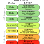
In these posts, we will document the fundamentals of networking. We will begin with the basics, including the OSI model, and work our way up from Layer 1 to layer 7, but mostly concentrating on Layers 1-3.
As many have learned, the path to success in troubleshooting networks is knowing and understanding the fundamentals.
OSI (Open Systems Interconnection) model:

Layer 7: Application Layer:
End users are interacting with the layer itself. When a user is being authenticated, that user is interacting with layer 7. If encryption is taking place, that is layer 6. The application layer determines if a remote communication partner is ready. For example if a modem is in use, the application layer asks if the modem is ready. Agrees on procedures for communication; data integrity, privacy and error recovery. Protocols running at layer 7: SMTP, POP3, Telnet, HTTP, FTP, SNMP.
Layer 6: Presentation Layer:
Formatting of data. For example if Word opens a file in gobbly gook, that is a presentation layer issue. No agreement has been made for formating. Compatability with the OS, ASCII, Binary, compression. JPG, MIDI, TIFF. Any file type is how data is being presented.
Layer 5: Session Layer:
Handles creation, maintenace and tear down of communication between hosts. The communication itself between two hosts is called a session. Sessions can be short. The session layer manages communication. Provides Full Duplex, Half Duplex, or Simplex. The Session Layer is commonly implemented explicitly in application environments that use remote procedure calls.
Layer 4: Transport Layer:
Establishes end-to-end connection between two systems. Session data is received from the upper layers and the transport layer makes sure the data gets to the destination in the correct sequence, and without errors. TCP (Connection-oriented) and UDP (Connectionless) are two methods of transporting data at the Transport Layer.
Layer 3: Network Layer:
IP runs at this layer, routers at this layer (routing layer), IP addresses, layer addresses, etc. Routing is a two question process: Is it a Valid path? And what is the Best Path to get there?
Layer 2: Data Link Layer:
This is where our switches and bridges run. WAPS also operate at this layer. Cable modems/DSL modems. Ethernet, HDLC, PPP, Frame Relay. There is a big difference between error detection and error recovery. Layer 2, we have error detection with FDS Frame Detect Sequence. MAC addresses/Hardware addresses/Physical Addresses/Burned In Address (BIA) are at Layer 2. There is such a thing as a layer 3 switch; a single device that can do the routing and the switching.
Layer 1: Physical Layer:
1’s and 0’s. The Physical Layer handles the actual data being transmitted. Cables, pins, voltage running at physical layer.
TCP:
- Guaranteed Deliver
- Error detection via sequence and ACK numbers
- Windowing
- Connection Oriented
TCP Three-way handshake: SYN, SYN-ACK, ACK.
Error detection is finding an error.
Error recovery is doing something about the error.
For example some layers have error detection – layer 1, but not error recovery.
In transmitting several segments, when the recipient sends the ACK number, it sends the next number in the sequence that the recipient expects to receive. An acknowledgement timer will re-send: Positive Acknowledgement with Retransmission (PAR).
Windowing is the amount of data that the sender is allowed to transmit without waiting for an ACK. The recipient decides the size of the window. This gives the recipient the ability to decide the amount of data flow. (Flow Control) Sliding Windows refers to dynamic adjustment of the size of the window itself.
UDP:
- Best effort delivery but no guarantee of delivery
- No error detection
- No windowing
- “Connectionless”
Cables:
Crosstalk – EM interference; a signal crosses over from one cable to another. Can be described as Near End Cross Talk (NEXT) or Far End Cross Talk (FEXT) depending on which end of the cable is being tested. PSNEXT is Power Sum Near End Cross Talk which is the calculation made when a NEXT test is run. When the NEXT result for each pair of wires is added, the result is the PSNEXT. (Not to be confused with the management software titled PSNEXT).
Straightthrough cable – used to connect a PC to a switch or a hub. The wire connected to Pin 1 on one side is connected to Pin 1 on the other, the wire connected to Pin 2 on one side is connected to Pin 2 and so forth.
CrossOver Cable – typically used between two switches, and when two switches are transmitting data over the same pair of wires, a crossover cable is used. A switch to switch connection with a CrossOver Cable is also called a TRUNK.
Rollover Cable – All eight wires in the cable will “roll over” to another pin at the remote end. eg. Pin 1 at one end rolling over to pin 8 at the other end. Pin 2 rolling over to pin 7 etc. Typically Blue Cisco cables that come with each Cisco router with a DB9 connector are Rollover cables. (Get a USB adapter so that you can use it with your laptop). These cables typically connect to the console port on the switch/router.
MAC address – Media Access Control Address (Also known as Ethernet/NIC/LAN/Physical/BIA address): used by switches to send frames to the proper destination. 48bit address.
The MAC address has two parts, the first being the Organizationally Unique Identifer (OUI). The OUI is assigned to hardware vendors by the IEEE. A given OUI is assigned to one and only one vendor. The second half of the MAC address is a value not yet used by that particular vendor.
The Broadcast MAC address: 77-77-77-77-77-77
The Multicast MAC address always starts with 01-00-5E, then 00-00-00 thru 7F-FF-FF
